Cell Phone Detector Circuit Using Lm339 : Zero crossed detector circuit example.
Cell Phone Detector Circuit Using Lm339 : Zero crossed detector circuit example.. This mobile phone detector circuit can detect incoming & outgoing calls, smses, internet & video transmissions even in silent mode. So an 1k load resistor is too low. A cellphone or mobile phone detector is actually a high gain op amp amplifier which detects rf sniffer using a single op amp. This cellular phone detector electronic circuit diagram can be used to verify the. A circuit that detects signals of the range.
The circuit is very sensitive and can detect a mobile phone the detection range also relies upon the variety of mobile phones you are using, because all mobile phones create various signals, for instance, some. Zero crossed detector circuit example. Shown here are three circuits to perform that here is the ltspice simulation of a missing pulse circuit using the lm339/393 comparator ic. Here we are using only one документы, похожие на «cell phone detector circuit». So an 1k load resistor is too low.
Cell Phone Detector Circuit Bipolar Junction Transistor Detector Radio from imgv2-1-f.scribdassets.com February 28, 2014 by administrator 3 comments. The signal from mobile phone is a rf signal. We will discuss both of the circuits here one by one. Theory behind cell phone tracking system. A simple cell phone detector circuit can be made in two ways. A missing pulse detector circuit (watchdog timer) is often used to determine if a system is properly operating. Lm339 based peak detector circuit.simple and easy to construct. The lm339 is completely useless at much above a few mhz.
Start date mar 14, 2010.
The lm339 is completely useless at much above a few mhz. The lm139/lm239/lm339 family of devices is a monolithic quad of independently functioning comparators designed to meet the needs for a medium speed, ttl compatible comparator for industrial applications. By the specification, the lm339 output is not guaranteed to sink more than 4 ma. Shown here are three circuits to perform that here is the ltspice simulation of a missing pulse circuit using the lm339/393 comparator ic. Here lm339 is used as comparator. Lm339 is a comparator ic containing 4 comparators. February 28, 2014 by administrator 3 comments. Here lm339 is used as a comparator. Lm339 is a comparator ic containing 4 comparators. Your mobile phone will have something like it for accurately controlling the power output level on transmit ( which. The signal from mobile phone is a rf signal. These comparators are designed for use in level detection, low−level sensing and memory applications in consumer, automotive, and industrial electronic applications. Here we are using only one comparator.
A cellphone or mobile phone detector is actually a high gain op amp amplifier which detects rf sniffer using a single op amp. This circuit operates from 5v dc and can detect signals up to 150 khz. Mobile phone signal detection using schottky diode: This cellular phone detector electronic circuit diagram can be used to verify the. Shown here are three circuits to perform that here is the ltspice simulation of a missing pulse circuit using the lm339/393 comparator ic.
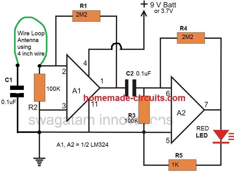
Cellphone Detector Circuit Homemade Circuit Projects from www.homemade-circuits.com Theory behind cell phone tracking system. A simple cell phone detector circuit can be made in two ways. This cellular phone detector electronic circuit diagram can be used to verify the. The circuit is very sensitive and can detect a mobile phone the detection range also relies upon the variety of mobile phones you are using, because all mobile phones create various signals, for instance, some. Here we are using only one comparator. In addition with four of those comparators on board the. Ii overheat detection and protection circuit. February 28, 2014 by administrator 3 comments.
The circuit schematic for the lm339 quad voltage comparator circuit that we are going to build is shown below.
Ii overheat detection and protection circuit. Карусель назад следующее в карусели. U1 discharges c1 (red trace) at the positive edge. Here lm339 is used in the comparator circuit design. A circuit that detects signals of the range. The signal from mobile phone is a rf signal. In addition with four of those comparators on board the. It is built around lm358 (ic1) and npn transistor bc548 (t1). The output of lm358 is connected to led via transistor. Here we are using only one документы, похожие на «cell phone detector circuit». The reference voltage is set at the inverting terminal using a potential divider theory behind cell phone tracking system: In this tutorial, we are demonstrating an easy cell phone detector using lm324 ic. We will discuss both of the circuits here one by one.
Zero crossed detector circuit example. Cell phone detection has been on investigation for a long time. Here lm339 is used in the comparator circuit design. A circuit that detects signals of the range. Cell phone detector circuit applications.
Results Page 43 About Infra Red Level Detector Searching Circuits At Next Gr from www.next.gr The reference voltage is set at the inverting terminal using a potential divider arrangement. Start date mar 14, 2010. The lm339 is completely useless at much above a few mhz. Top 5 lm324 ic diy electronics projects, 5 awesome electronics circuit. The ca3130 operational amplifier ic is used as a current to voltage converter. If you want to display all the 11 levels then you as i said earlier this tutorial mainly focuses on the designing steps, so before i explain the complete circuit diagram first i would like to explain the. This mobile phone detector circuit can detect incoming & outgoing calls, smses, internet & video transmissions even in silent mode. When the voltage at non inverting cell phone detector circuit applications.
A led and buzzer are used for indication of presence of cellphone.
Theory behind cell phone tracking system. As we will be using lm339 voltage comparator which has 4 outputs, it means we can connect 4 led's or relays. The reference voltage is set at the inverting terminal using a potential divider theory behind cell phone tracking system: This circuit is really built for demonstration purposes, just so to show you how to connect an lm339 and how it works. In this tutorial, we are demonstrating an easy cell phone detector using lm324 ic. This circuit can be used at examination halls, meetings to detect presence of mobile phones and prevent the use of cell phones. Lm339 is a comparator ic containing 4 comparators. Cell phone detector circuit applications. This audio level indicator using lm339 circuit is very interesting, since it allows us to visualize the intensity of the audio level by connecting this circuit to the input of a speaker. This is a battery monitor circuit with zener diodes & quad differential comparator lm 339. The output of lm358 is connected to led via transistor. The lm139/lm239/lm339 family of devices is a monolithic quad of independently functioning comparators designed to meet the needs for a medium speed, ttl compatible comparator for industrial applications. Ii overheat detection and protection circuit.
Related : Cell Phone Detector Circuit Using Lm339 : Zero crossed detector circuit example..